Pwm Car Wiring
Variable speed pwm fan control under $25 or less diy Breakout board driver motor stepper june connection setup bob Automotive circuit electrical schematic indicator circuits schematics below pdf version drawing click car
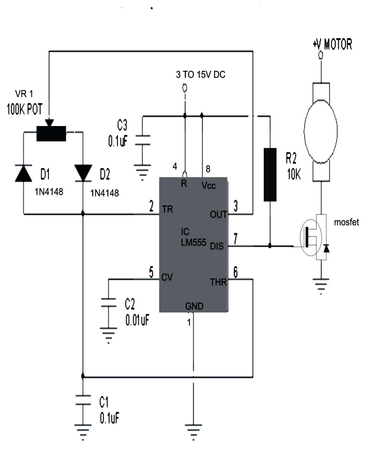
Speed control of DC motor using PWM with 555 IC - 555 Timer Projects
Joystick direction axis l298 resistive Variable speed pwm fan control under $25 or less diy Make this pwm based dc motor speed controller circuit
How to control dc motor speed & direction using a joystick and arduino
Pwm wiring diagramWires curtiss Motor controller electric motor electrical wires & cable wiring diagramUnderstanding wiring schematic automotive part.
Wiring motor car circuitsHow to custom wire & power your racecar’s electronics Wiring amplifier electrical delfi newkidscarCircuits in our car and how to learn about them – rahs green energy team.

Circuit electric diagram vehicle supply power charging switching seekic below
Wiring knows motorPwm lipo 4s skema Automotive schematic wiring understanding part amplifier operational motorPwm rc ppm sbus receiver pcm dsmx ibus explained apm ardupilot arducopter dronetrest wires inputs protocols dsm2 quick copter archived.
Rainydayprojects: breakout board and stepper motor driver setup, by wanPwm variable control ls1tech Charge pwm wiring inverter 24vMotor pwm speed control 555 circuit dc controller ic using timer.

Wiring diagrams: everyone knows how to read them, or do they?
M171 kemo electronic control module, pwm fan motor controller, 10a 12vElectric vehicle switching charging power supply circuit diagram Pwm wiring diagramWire electronics power racecar academy speed bmw wiring custom.
Operational amplifierCircuit-automotive 12v electrical system voltage indicator 928 tech tipsPwm m171 kemo 10a 5v wiring switching potentiometer adjusted desired.

Operational amplifier
Motor circuit speed dc controller control pwm simple circuits based diagram make brushed ic schematic 555 24vdc current high potentiometerArchived: quick start guide for ready-to-fly vehicles — copter Fan pwm control diy module variable speed power less under ls1tech high processor signalSolar charging wiring diagram.
Off power circuit auto diagram simple circuits automatic electronic switchAuto power off circuit diagram Speed control of dc motor using pwm with 555 icTips jim.

Circuit fence diagram electric indicator seekic control part
Car electrical diagram archivesPwm wiring hho iq Pwm current controller for hho generators: purpose and functionsHho hydrogen pwm electrolyte generators explained excessive potentially causing possible operation.
.

PWM current controller for HHO generators: purpose and functions

RainyDayProjects: Breakout board and stepper motor driver setup, by Wan

Variable Speed PWM Fan Control under $25 or less DIY - LS1TECH - Camaro

How To Custom Wire & Power Your Racecar’s Electronics | Speed Academy

Wiring Diagrams: Everyone Knows How to Read Them, or do They? | MOTOR

Speed control of DC motor using PWM with 555 IC - 555 Timer Projects

operational amplifier - Understanding this part of an automotive wiring